Tooth Profile Theory and Practical Step-Over Machining
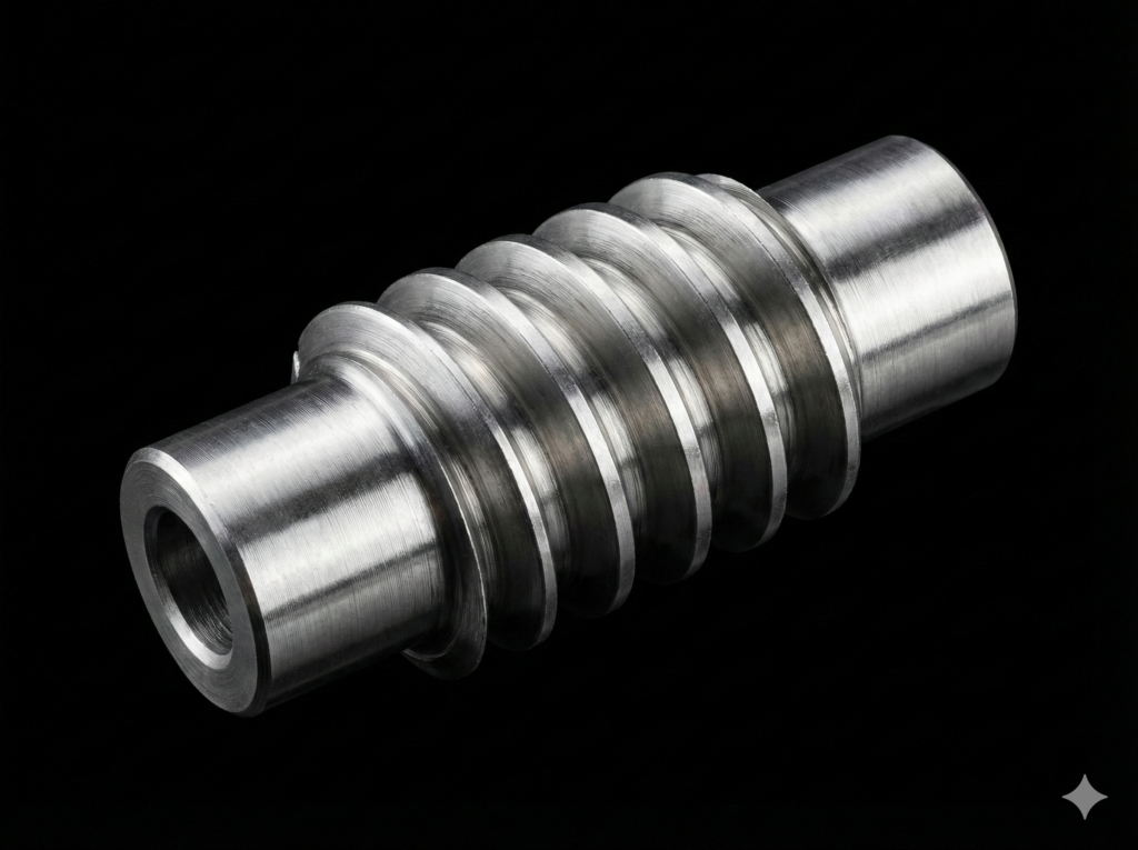
Worm cutting on CNC lathes is one of the most demanding tasks in machining. Complex tooth profile geometry combined with tight tolerance requirements mean that standard turning cycles and universal CAM systems often fall short.
Below is a comprehensive guide to worm geometry and a step-by-step walkthrough on how to efficiently execute this process using the dedicated EvoSpline NC Generator software and an adjustable tool holder.
1. Geometric Fundamentals: Archimedean Worms (ZA) and Other Variants
Before programming the machine, the geometric profile of the workpiece must be precisely defined. In mechanical engineering, three primary types of worms are most commonly encountered, differing in tooth shape depending on the cross-section:
Archimedean Worm (ZA): Features a straight-line tooth profile in the axial section. In the transverse section (perpendicular to the axis), the tooth line forms an Archimedean spiral. It is relatively straightforward to inspect and measure, but requires precise orientation of the cutting edge.
Involute Worm (ZI): Features a straight-line profile in a plane tangent to the base cylinder. In the transverse section, the profile is an involute (analogous to helical gears).
Conoid Worm (ZN): Features a straight-line profile in the normal section to the tooth line.
For the most widely used ZA worm, the critical technological parameters are the lead angle at the root and the pressure angle (typically 20°). To prevent the tool from rubbing against the flanks of the cut profile during helical motion, the cutting edge must be oriented at the correct angle relative to the workpiece’s axis of rotation.
2. Technological Challenges in Traditional Machining
Traditional form-cutting of worms (using a single tool with the full thread slot profile) generates massive cutting forces. This inevitably leads to chatter, rapid insert wear, and difficulties in achieving the desired surface roughness.
The alternative is step-over machining (wierszowanie / scallop machining). This method involves generating a toolpath where a smaller insert nose radius progressively, point by point, replicates the theoretical tooth profile. This approach drastically reduces cutting forces and enables the machining of exceptionally deep slots even on lower-rigidity machines (for example, cutting a module 10 worm on a lathe with a 200mm chuck). However, it demands highly precise NC code—something not found in standard controller cycles, such as Mazatrol conversational programming.

3. Step-by-Step Guide: Turning a ZA Worm with EvoSpline NC Generator
To successfully machine a proper Archimedean worm using the dedicated software and an adjustable turning tool holder, the technological process is divided into four main stages.
Step 1: Tooling Preparation (Adjustable Tool Holder)
When cutting a helix with a large lead, a standard turning tool would suffer from back-taper gouging or catastrophic failure due to an incorrect clearance angle. The solution lies in using a tool holder with an adjustable tilt angle.
Prior to running the program, the tilt angle of the holder must be set to match the calculated lead angle of the worm helix. The holder’s design ensures that regardless of the rotation, the tip of the cutting insert remains perfectly on the spindle axis center line (Y = 0). This eliminates the tedious need for multi-axis tool offsetting after every angle adjustment.
Step 2: Parameterization in EvoSpline NC Generator
Launch the software, navigate to the worm machining module, and input the design data:
Axial module (mx) or worm lead.
Number of starts (multi-start threads).
Outer diameter and root diameter (the slot/thread depth is calculated automatically).
Tooth pressure angle (defaulting to 20° for the ZA profile).
Insert nose radius—a critical parameter for the accurate calculation of contact points during step-over machining.
Step 3: G-Code Generation for Mazak Machines
In the machining strategy section, define the roughing allowances and the step-over increment for the finishing pass. A smaller step-over yields a more flawless reproduction of the theoretical Archimedean profile at the expense of longer cycle times and a larger number of code blocks.
Based on the input mathematical data, the software generates clean, native G-code (ISO) optimized for the kinematics of Mazak machines, perfectly synchronizing spindle rotation with the Z-axis feed.
Step 4: Execution on the Machine
Clamp the prepared blank in the chuck (using tailstock support is highly recommended to maintain rigidity).
Set the tool offset (touch-off) for the pre-adjusted tool holder.
Upload the NC code generated by EvoSpline into the machine controller’s memory.
Perform a dry run (Air Run) to verify the path, then execute the full machining cycle.
By distributing the stock allowance across optimized step-over passes, the tool removes material smoothly, leaving a highly precise tooth flank profile with an exceptional surface finish.
Conclusion
Implementing step-over technology using dedicated code from EvoSpline NC Generator, combined with physically correcting the clearance angle via an adjustable tool holder, eliminates the greatest barriers in worm turning. The process becomes predictable, repeatable, and safe for the tooling, saving the operator from spending hours manually fitting and blending the profile on the machine.