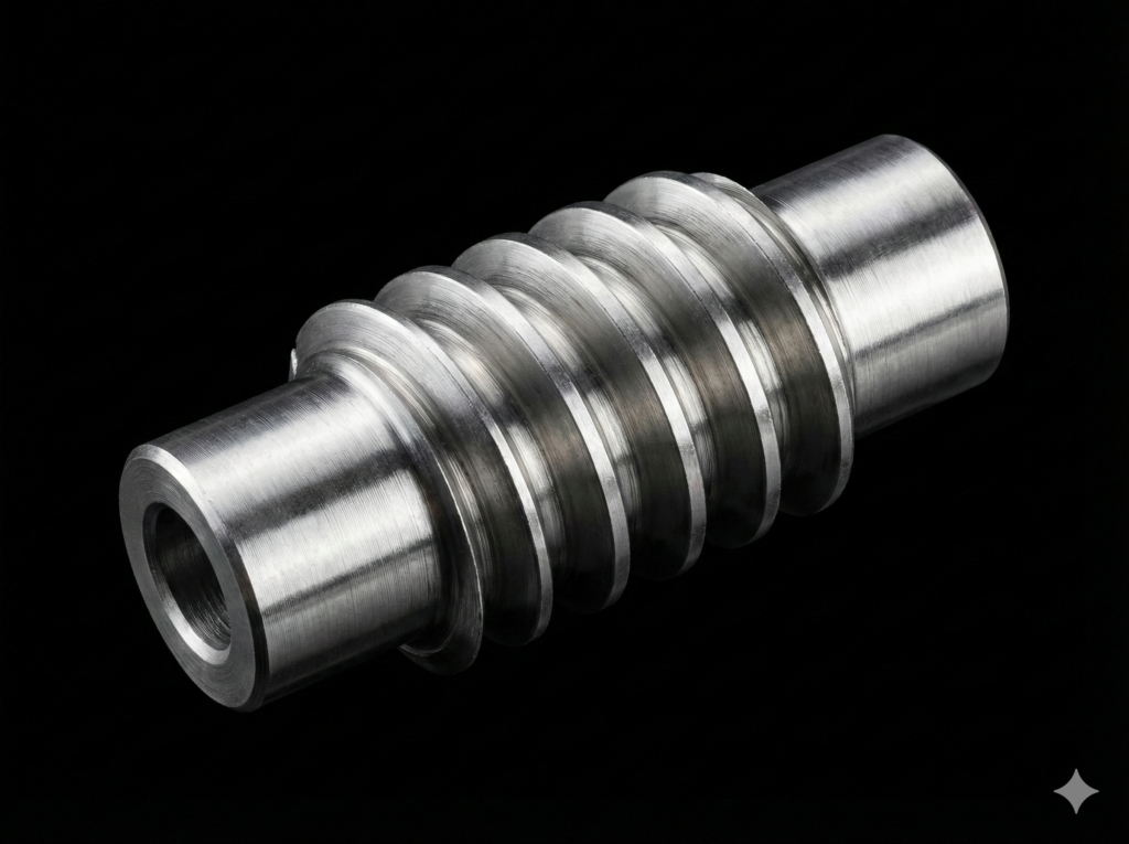
Unlike classic gears, where the pitch diameter is determined simply by the number of teeth and the module, the diameter of a worm is, to a certain extent, an autonomous parameter. Its incorrect selection carries severe consequences: from a drastic drop in efficiency and gearbox overheating to fatigue failure of the shaft under load. So, how do you find the sweet spot? If you want to understand where the worm diameter comes from, read on!
1. The Key Parameter: Diameter Factor q
To standardize the design process and limit the number of manufacturing tools (such as modular hobs for worm gears), the concept of the worm diameter factor q was introduced. It is defined by a simple ratio of the worm pitch diameter (d1) to its axial module (m):
In engineering practice, the values of q are standardized and usually fall within the range of 7 to 25 (e.g., 8, 10, 12, 16, 20).
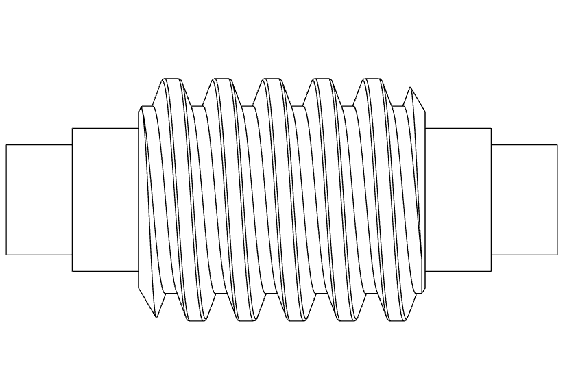
- Low q values (e.g., 8–10): The worm is “slender” and thin relative to the tooth size (module).
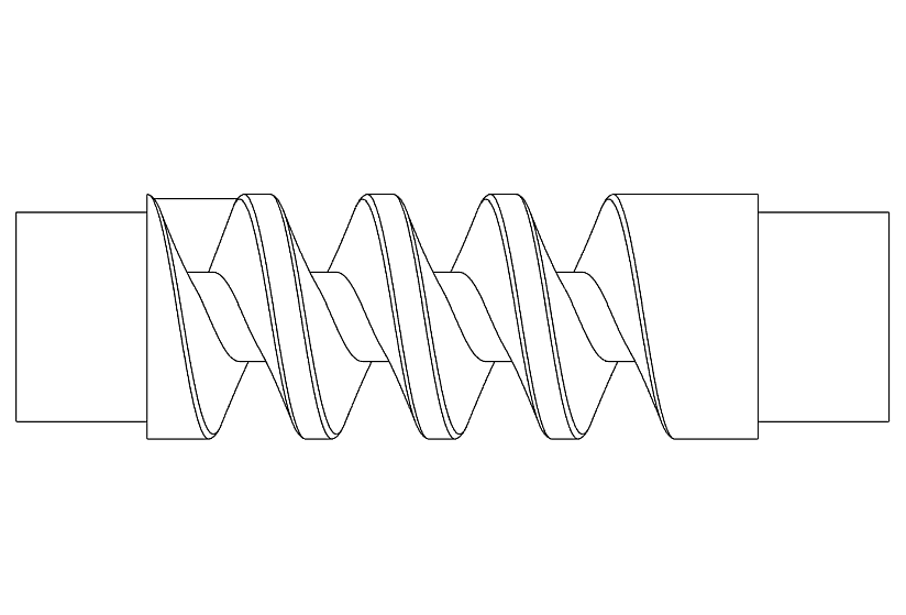
- High q values (e.g., 16–20): The worm is “thick,” resembling a massive shaft with a shallowly cut thread.
2. Geometry vs. Efficiency: Why We Want “Slender” Worms
From a tribological perspective, the designer’s goal is always to achieve the highest possible gearbox efficiency. The main factor generating losses in this mechanism is high sliding friction. This efficiency depends directly on the lead angle of the worm thread.
The geometric relationship is absolute:
Where z1 is the number of starts (threads) of the worm.
Analysis of this formula leads to a clear conclusion: the smaller the diameter factor q (meaning the smaller the worm pitch diameter d1), the larger the lead angle of the thread line. In turn, a higher lead angle means lower friction losses, lower operating temperatures, and significantly higher gearbox efficiency. Driven by energy efficiency goals, a designer naturally wants to minimize the worm diameter as much as possible.
3. The Physical Barrier: Core Strength and Shaft Deflection
At this point, however, we encounter the realities of the strength of materials, where physics brutally challenges theoretical efficiency. A worm is rarely a separate slip-on component; most frequently, it is an integrated, bearing-supported shaft.
During gearbox operation, inter-tooth forces generate massive radial and axial loads. The radial force tends to deflect the worm shaft, which drastically alters the contact geometry between the teeth and the worm gear (causing edge load concentration) and leads to accelerated profile wear.
If we overdo the reduction of the diameter (too low a q value), the worm root diameter becomes dangerously small. Since the bending strength of a shaft increases to the third power relative to its diameter, even a minimal reduction in the root diameter drastically lowers the rigidity of the entire component.
The results?
- Increased bending and torsional stresses in the core.
- Risk of fatigue failure at the root of the threads under full industrial load.
- The necessity to use expensive, high-alloy case-hardening steels (e.g., 18CrNiMo7-6) to compensate for the lack of rigidity with sheer material strength.
Summary: How to Make the Design Decision?
In practical engineering, selecting the worm diameter is an iterative process based on the following framework:
- Drive Applications (continuous duty, high power): Efficiency is the priority. Multi-start worms (z1 = 2, 3, 4) and the lowest possible q values (typically 8–12) are selected. Core rigidity is ensured through rigorous shaft deflection calculations and advanced thermochemical heat treatment.
- Positioning and Lifting Applications (intermittent duty, manual drives): Efficiency is secondary, and self-locking is often desired. Single-start worms (z1 = 1) and high diameter factors q (14–20) are applied. The worm features a massive, rigid core, allowing it to be manufactured from more economical materials (e.g., C45) without the risk of failure.
Understanding this correlation separates theoretical CAD drawing from conscious mechanism design that will operate failure-free for years.