When machining standard ISO metric or unified fastening threads, structural limitations of the cutting tool are rarely a concern. The helix angle of such threads is typically small (often under 3°–4°), allowing a standard lathe toolholder to easily handle the clearance without issues.
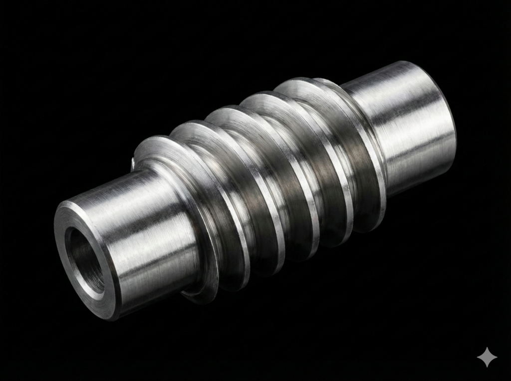
However, the reality of machining Archimedes worms is entirely different. Here, we routinely face large pitches, multi-start profiles, and relatively small diameters. In such an industrial environment, using a standard threading toolholder is a direct recipe for tool destruction. To machine a high-quality worm, you must utilize a toolholder with an adjustable helix angle (tilt angle). Here is why.
1. The Kinematic Clearance Angle Problem
Every indexable insert has a specific static clearance angle designed to prevent the tool’s flank face from rubbing against the machined material. During the threading process, however, the tool moves dynamically along both the Z and X axes. This dual-axis motion creates a dynamic (kinematic) helix angle (ϒ).
If you use a rigid, standard toolholder (fixed at 0° tilt), the insert is positioned perfectly perpendicular to the rotary axis of the workpiece. As the worm’s helix angle increases, the effective clearance angle on one side of the insert drastically decreases, while on the other side, it increases excessively.
2. Flank Rubbing and Profile Distortion
What happens when the dynamic helix angle exceeds the tool’s built-in clearance angle?
- Flank Face Rubbing: The “heel” of the carbide insert begins to rub heavily against the side flank of the worm thread.
- Friction and Heat: This rubbing generates extreme temperatures, causing rapid chipping of the cutting edge and premature tool failure.
- Production of Defects: The friction physically deforms the flank of the worm, destroying the surface finish and altering the critical pressure angle. The generated NC code might be mathematically perfect, but the physical part will end up in the scrap bin.
3. The Mathematical Solution: Matching the Helix Angle
To restore optimal and symmetrical cutting conditions, the insert must be tilted so that its axis of symmetry aligns perfectly with the helix angle of the worm thread. The required tilt angle is calculated using the geometric relationship:
Where L is the lead of the worm thread and d1 is the pitch diameter.
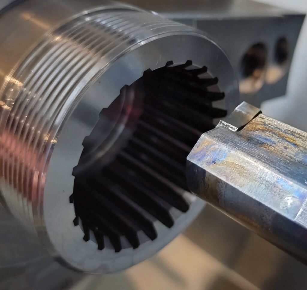
Adjustable toolholders feature a pivoting head or specialized interchangeable shim seats (anvils) that allow the user to mechanically tilt the insert by the exact angle γ derived from the calculations.
Summary: The Benefits for CNC Machining
Implementing an adjustable-angle toolholder in combination with high-precision ISO code from the EvoSpline NC Generator ensures:
- Symmetrical Cutting Forces: Equal load on both sides of the insert, preventing tool deflection.
- Flawless Surface Finish: Complete elimination of flank rubbing, which is critical if the worm is meant to operate directly after turning or is being prepared for subsequent grinding.
- Maximum Tool Life: Carbide inserts wear down evenly, drastically reducing tooling costs in mass production.
For demanding machining cycles—especially when utilizing universal inserts like the VBMT supported by the EvoSpline NC Generator software—proper tool orientation relative to the helix line is the final piece of the puzzle to achieve full reliability.