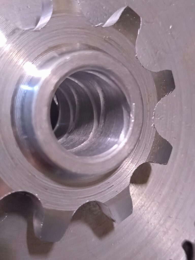
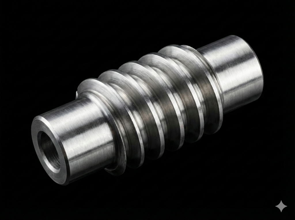
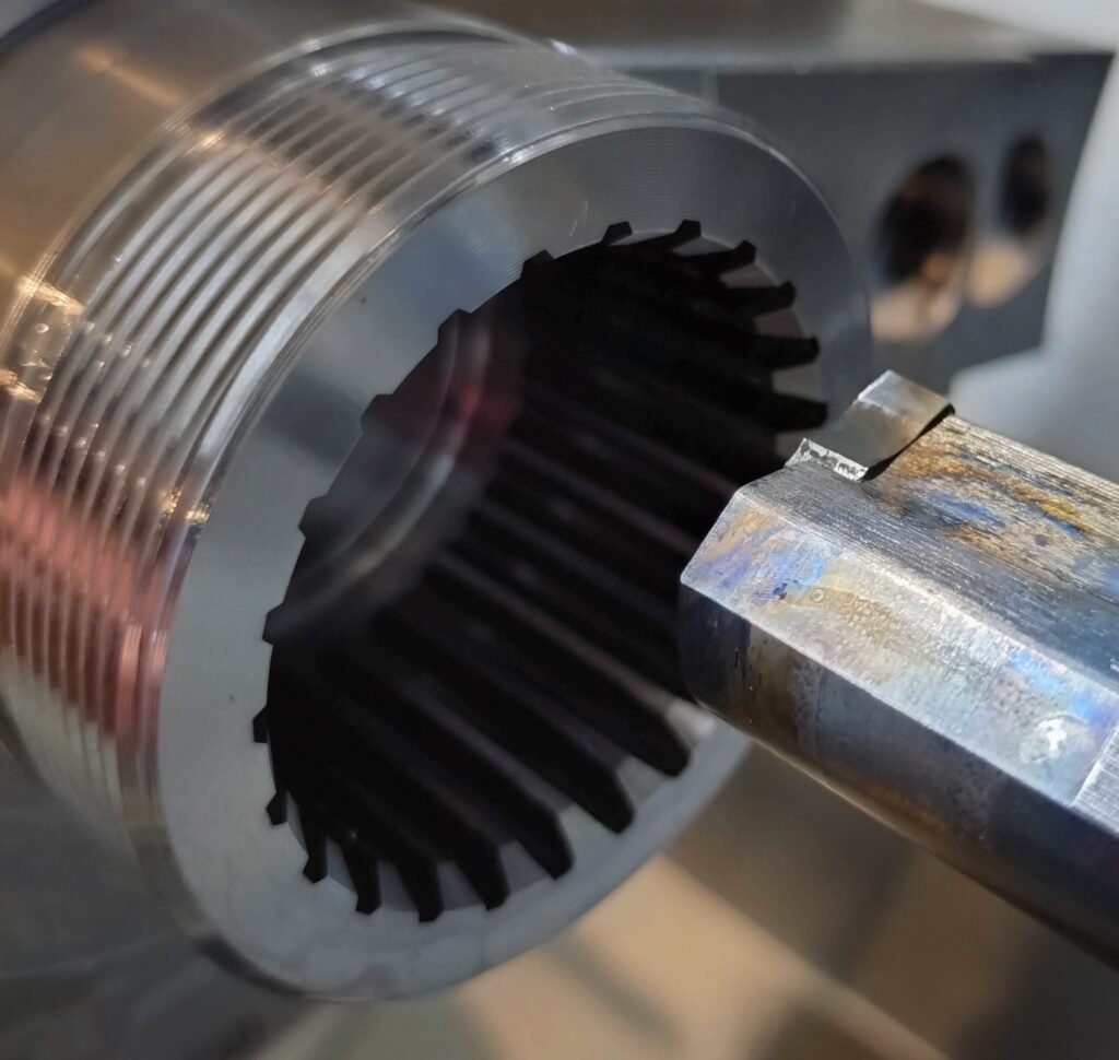
Oil grooves are most commonly found in bushings and journal bearings. They can also often be seen in the bores of gear housings. The purpose of such a groove is simple – it distributes lubricant evenly inside the bore. How do you machine it on a CNC lathe?
Often, these grooves are made using special tools using the threading method. You set the pitch, spindle speed, and in a few passes, the groove is completed. This is a very fast and efficient method. However, it is suitable mainly for larger production series due to the cost and requirement of a specialized tool.
What if I don’t have or don’t want to use a special tool?
I’ve had this dilemma many times. The solution was not difficult at all – in fact, it was right within reach. I just had to look differently at a tool I was already using.
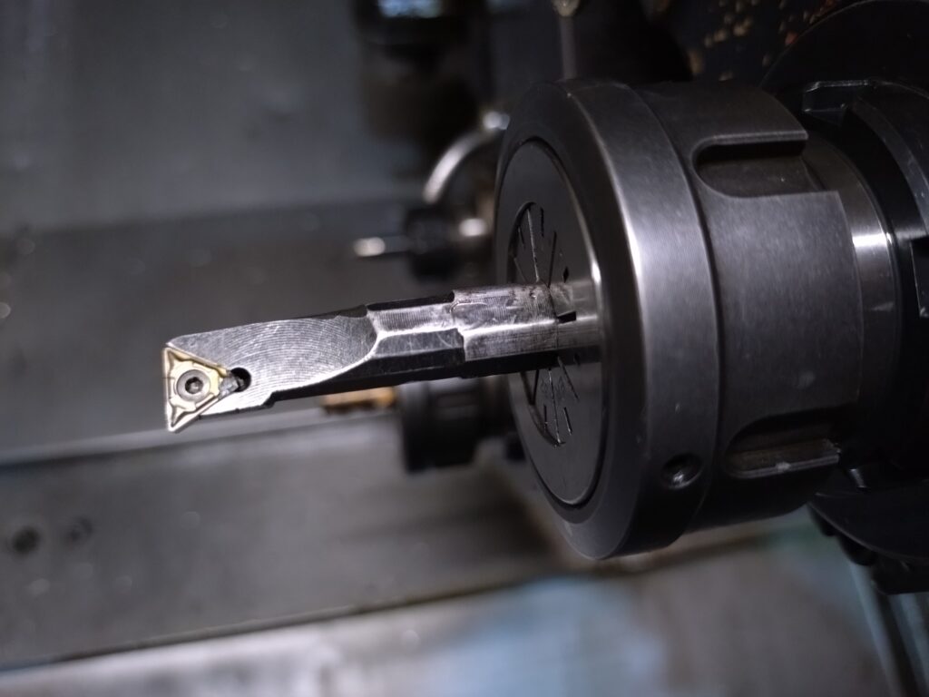
I am talking about a boring bar, although a standard boring bar cannot efficiently machine with a feed rate of 15 mm/rev. The helix angle of an oil groove exceeds the capabilities of such a tool several times over. But what if we mount the boring bar in a driven (live) tool holder? Then it becomes an end mill! And that is the whole secret.
I think everyone has a suitable boring bar in their shop – one that can be used, for example, for an undercut or relief groove (using TCMG or DNMG inserts, i.e., triangular and 55° rhombic). It is important that the cutting circle diameter resulting from the rotation of this tool is significantly smaller than the diameter of the bore in which we want to make the groove. Can you use a thread mill instead? Yes, but only one with a single row of teeth.
How to get started with machining the oil groove?
- Mount the boring bar in the live tool holder.
- Measure it just like you measure a boring bar – in the Z and X axes. This will make things much easier.
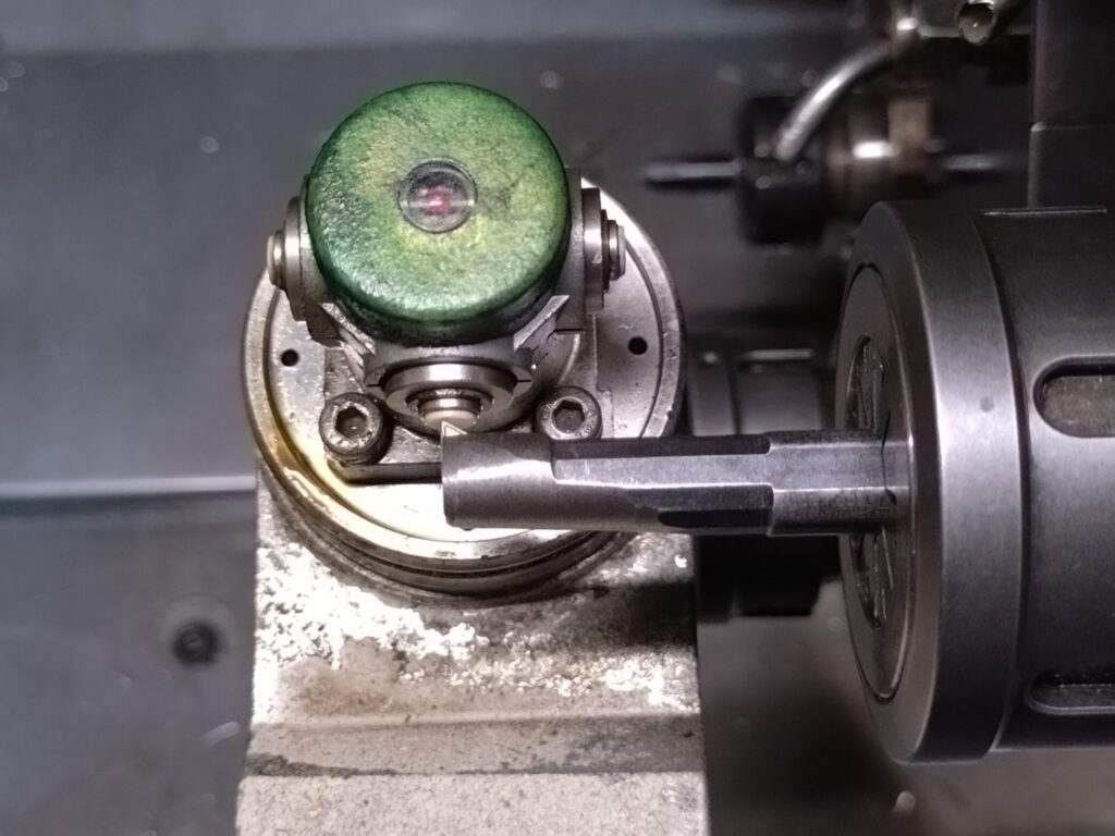
You could, of course, measure it like an end mill (only in the Z axis, taking the X axis as the rotation center of the holder), but then you would have to recalculate everything. We will stick to measuring in the X axis. Thanks to this approach, all dimensioning in the program will be exactly as if you were simply boring a hole. If your lathe requires a tool description, you can treat this boring bar as an end mill.
We have the tool, but without a program, we can’t do anything. Since I work on Mazak machines, I use Mazatrol daily. However, it will be easier for us to write this operation in standard G-code (ISO). It’s just a few lines of code. You can create a template so that for future cases you only need to change the pitch, diameter, depth, etc.
G-Code
M200
G53 X0. (USING MACHINE COORDINATES MAKES IT EASIER FOR THE TURRET TO RETURN HOME IN THE X AXIS - FOR MAZAK MACHINES)
T0101 M8 (TOOL SELECTION)
M203 S100 (SOME MACHINES REQUIRE LOWER STARTUP RPM TO ENGAGE THE DRIVEN HOLDER CLUTCH)
S3333
G0 X30.6 Z1. C0.
G1 Z0. F50
G1 Z-36. H864. (GROOVE MILLING OPERATION)
G0 X29.
G0 Z10.
G53 X0.
M30
I used the H axis here – this is the C axis in incremental mode. I enter how many degrees the C axis should rotate, not what absolute position to set. This makes things much easier, and as you can see, the program is short and simple.
Of course, you must account for differences between machines. The name of the incremental axis for the C axis may vary on other controls. In this program, I assumed that asynchronous feed rate and constant spindle speed are enabled by default. I use 3333 RPM for a boring bar with a 10 mm diameter. The larger the tool diameter, the lower the RPM, of course.
How to make a version with two grooves of opposite hand/direction?
Simply copy a few lines and change the sign for the H value:
G-Code
M200
G53 X0.
T0101 M8
M203 S100
S3333
G0 X30.6 Z1. C0.
G1 Z0. F50
G1 Z-36. H864. (GROOVE MILLING OPERATION)
G0 X29.
G0 Z1.
G0 X30.6 C0.
G1 Z0. F50
G1 Z-36. H-864. (GROOVE MILLING OPERATION IN OPPOSITE DIRECTION)
G0 X29.
G0 Z10.
G53 X0.
M30
How to calculate pitch and rotation angle H?
Where does pitch F come from in this program? It comes from the ratio of distance in the Z axis to the angle through which the spindle rotates (H).
Formula for pitch F:
Plugging in the values from the example:
The pitch in the example program is equal to 15 mm. If you want to calculate the H value for a specific distance Z and pitch F, use the following formula:
Important note: When you finish and remove the boring bar from the live holder, don’t forget to restore the correct offset and coordinate in the X axis!