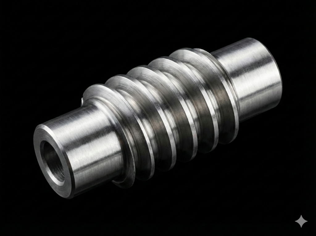
In machine design theory, a worm gear drive is a specific case of a gear mechanism with crossed axes. In workshop practice, it represents one of the greatest manufacturing challenges. The most common mistake when attempting to reverse-engineer or design such a drive is a fundamental misunderstanding of the difference between the axial module and the normal module.
An error in interpreting these values does not merely mean that a tooth will be slightly too thick or too thin – that is something you can easily compensate for on the machine controller. A mistake here means an incorrect pitch. In a worm gear drive, even a minimal deviation in pitch creates an error that prevents proper tooth engagement, leading to rapid destruction of the mechanism.
1. Three Planes: What Are These Modules?
To understand the geometry of a worm, we must look at it through cross-sections in three different directions. In each of these sections, the distance between the teeth (the pitches) will be completely different, and consequently, the module values will differ as well:
- Axial Module (mx): Determined in the longitudinal (axial) cross-section of the worm. This is the crucial parameter for a CNC lathe programmer because it relates directly to the machine’s feed rate in the Z-axis. The axial pitch (Px=π⋅mx) is simply the distance between corresponding profiles of adjacent teeth, measured parallel to the axis of the shaft.
- Normal Module (mn): Determined in the cross-section perpendicular to the tooth helix line (i.e., at the lead angle γ). The normal pitch (Pn) is always shorter than the axial pitch, and this difference increases as the worm’s lead angle grows.
- Transverse Module (mt): Determined in the transverse cross-section, perpendicular to the worm axis. It is rarely used directly in worm turning operations, but it is geometrically essential for linking the pitch diameter with the number of starts or teeth.
The relationship between the two most critical modules is defined by a rigid formula:
2. The Sacred Pitch: How Manufacturing Differences Arise
The most important rule to remember is the absolute symmetry of pitches between the worm and the worm wheel. Simply using a specific tool does not automatically dictate the design system of the entire gear drive. The dependency works both ways:
- Scenario A: If you hob a worm wheel using a universal, off-the-shelf gear hob with a standardized normal module (mn), the mating worm CANNOT be cut with a random axial pitch. You must calculate a dedicated axial module for this specific worm (mx=mn/cos(γ)) and turn it on the lathe with that exact (and often fractional) axial pitch.
- Scenario B: If you turn a worm using a pitch based on a clean, even axial module (mx) (e.g., mx=4, because it is the most convenient way to thread-cut on a lathe), you must cut the mating worm wheel with a hob of the exact same corresponding module. Usually, a fly cutter or a custom hob that perfectly mirrors the specific worm’s geometry is used in this case.
Why is pitch so critical? If you make a mistake with the tooth thickness on the lathe, you can apply a tool correction, cut slightly deeper, and adjust the backlash. However, if you confuse the modules and assume the axial module value is equal to the hob’s normal module when cutting the worm, you ruin the pitch. The worm teeth will engage at different positions along the worm wheel circumference than those generated by the hob. At best, the gear drive will be noisy; at worst, it will fail rapidly.
3. Fast Module Matching in EvoSpline NC Generator
In everyday workshop practice, controlling a CNC machine via the axial module is the most convenient method. Control systems (such as ISO G-code or Mazatrol) require a clean thread lead in the Z-axis, calculated directly from the axial pitch and the number of starts:
For this reason, the input value for generating the toolpath in EvoSpline NC Generator is always the axial module (mx).
However, as the software developer, I am fully aware of real-world machine shop conditions and the challenges of manufacturing replacement parts to match existing worm wheel hobs. Therefore, I equipped the application with a dynamic geometric calculator.
As you enter or finely adjust the axial module value, the program calculates and displays the corresponding normal module (mn) “on the fly” in real time.
Thanks to this, the programmer standing in front of the monitor does not have to flip through reference tables or manually calculate trigonometric functions. If you know you have a worm wheel hob with a normal module of mn=4.00, you can adjust the axial module in EvoSpline step-by-step in a fraction of a second until the normal module field displays a perfect 4.00. The program instantly factors in this specific pitch, recalculates the insert nose radius (e.g., VBMT), and generates flawless NC code.
Summary
Pitch is the foundation of any worm gear drive. Whether your starting point is a standard modular cutter (normal system) or lathe machining convenience (axial system) – both worlds must align perfectly. Tools like EvoSpline NC Generator eliminate the risk of mathematical errors from the programmer’s shoulders, allowing you to focus on what matters most: clean, precise, and efficient machining.