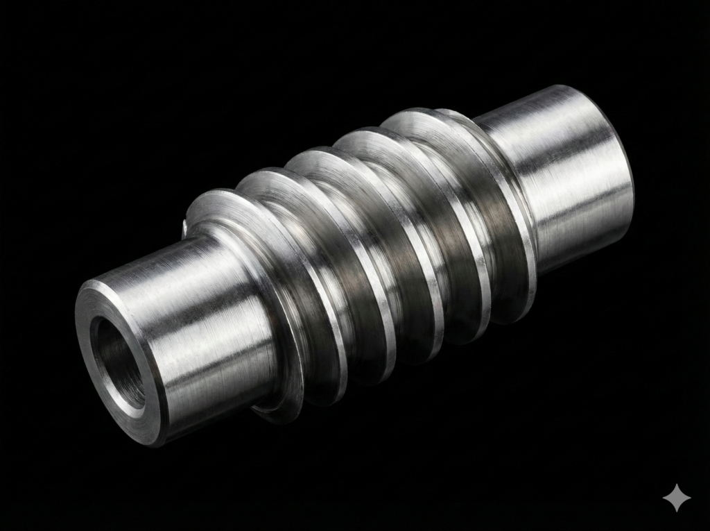
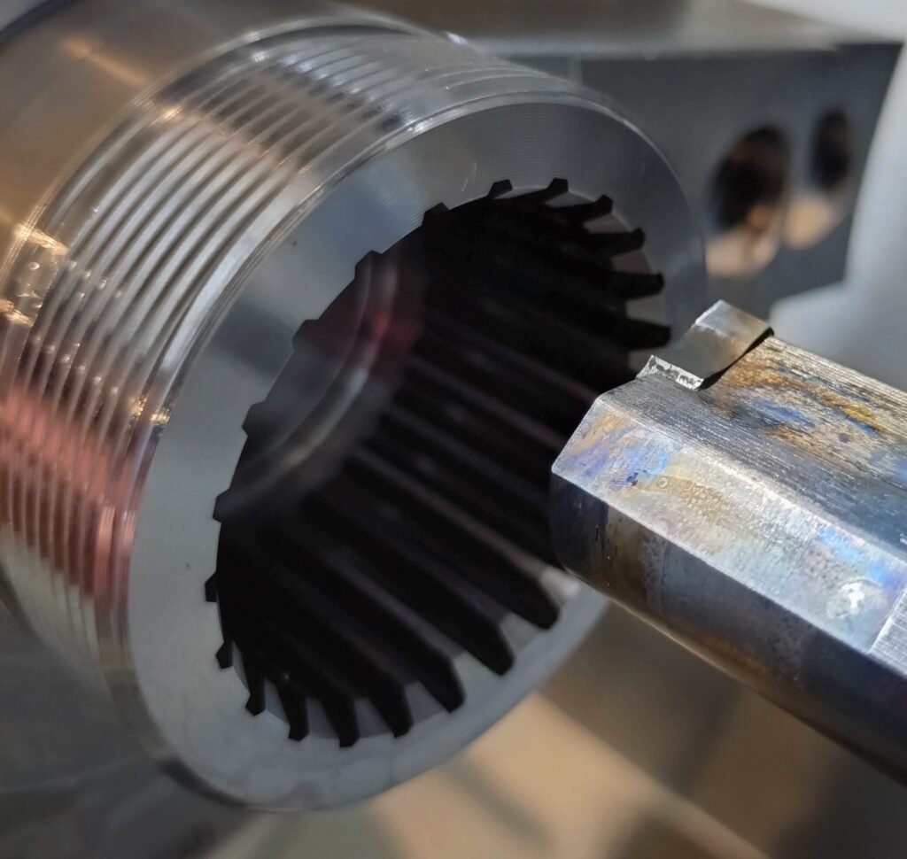
Reverse engineering parts from a physical sample is the bread and butter of any machine shop. While replicating a standard shaft or bushing poses no challenge, decoding the geometry of a worn or damaged gearbox worm can be a technological nightmare. The critical parameter we must identify is the module (m). The entire tooth profile and the proper engagement with the mating worm gear depend directly on it.
How do you approach this when no technical drawing is available? Here are two methods—ranging from a quick caliper verification to an uncompromisingly accurate CNC lathe trick that allows you to differentiate between the axial and normal module.
Method 1: Quick Workshop Measurement (Vernier Caliper)
The simplest method for an initial estimation is measuring the thread lead (Ph) or the axial pitch (Px) using a vernier caliper. Instead of measuring the distance between two adjacent teeth (which introduces a massive error on a worn part), it is best to measure the distance across multiple thread starts—selecting those sections of the worm that are in the best mechanical condition.
The Golden Rule of Measurement: You must place the caliper jaws at identical points on the same side of the tooth profile (e.g., from the left flank of the starting thread to the left flank of the ending thread). Once you have measured the distance (L) across a number of pitches (N), calculate the lead (Ph). Then, knowing the number of starts on the worm (z1), you can determine the axial pitch:
Knowing that the axial pitch is Px=π⋅mx, you can easily calculate the axial module (mx):
However, the caliper method has a significant drawback: due to the difficulty of perfectly aligning the tool with the part axis and the wear on the edges, accuracy rarely exceeds ±0.1 mm. That is not enough for absolute certainty.
Method 2: The CNC Lathe Trick – Micron Precision with a Strip of Paper
If the worm needs to be replicated with flawless precision, it is worth moving the measurement to a CNC lathe. A lathe, with its axis positioning accuracy down to thousands of a millimeter, will act as a perfect coordinate measuring machine.
1. Clamping and Approach (Setting the Base)
Mount the worm in the lathe chuck (support with a tailstock if necessary). Load a tool with a universal rhombic insert (such as a VBMT) into the turret. Jog the tool into the worm groove and establish a specific diameter along the X-axis. This does not need to be the pitch diameter; it is only critical that this X position remains identical for both measurement points.
2. Measuring the Initial Point (The Paper Method)
Slide a narrow strip of thin paper between the side flank of the VBMT insert and an undamaged, clean flank of the worm thread. Very slowly (using the handwheel MPG) jog along the Z-axis until the paper is gently trapped between the cutting edge and the part. At this exact position, zero the Z-axis in your coordinate system.
3. Traversing Across Multiple Leads (Reading the Distance)
Retract the X-axis to a safe distance, move the Z-axis several pitches down the worm (selecting another clean flank on the same side of the tooth), and feed the X-axis back to the exact same baseline diameter. Repeat the paper strip procedure. Read the value that the Z-axis has moved directly from the screen (ΔZ).
Mathematical Verification: Axial Module vs. Normal Module
With the precise reading from the machine’s Z-axis (ΔZ), we can proceed to the mathematical analysis. Let’s assume we measured the distance across N full pitches, and our worm has two starts (z1=2).
Determine the actual lead:
Determine the axial pitch:
Calculate the hypothetical axial module:
This is where the greatest advantage of the CNC method becomes apparent. Off-the-shelf tooling (such as hobs for worm gears) is manufactured to strict standards: based either on the axial module (mx) or the normal module (mn). Thanks to micron-level measurement precision, the resulting value will allow you to immediately decipher the gearbox designer’s intent:
- If mx turns out to be a clean whole number or half-integer (e.g., 3.00, 4.00, 4.50), the worm was designed using the axial profile cross-section.
- If the calculated mx is a “strange” fractional number (e.g., 4.132), it means the design was based on the normal module (mn) due to a steep helix lead angle (γ). In that case, convert it using the formula:
Even with a relatively small helix angle, the accuracy of the CNC lathe will flawlessly expose this difference, protecting you from producing a scrap part.
Summary
Using a CNC lathe as a coordinate measuring machine is a simple and brilliant way to eliminate the uncertainty of manual hand measurements. Combining the “paper method” with calculation algorithms provides 100% certainty before you even begin generating new G-code in the EvoSpline NC Generator. A prudent technologist measures twice on the machine to cut a perfect profile on the very first try.