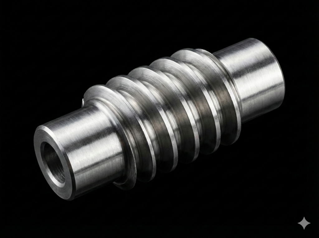
In the previous article, I discussed how the integrity of the pitch is absolutely critical for the survival of a worm gear drive. Another equally vital geometric parameter that determines whether the components will mesh at all is the tooth helix angle.
While in classic helical gears the helix angles of both mating gears are identical, a worm gear drive operates under different rules dictated by the specific, helical geometry of the worm. So, how do you properly determine this angle for a worm wheel, and what must you strictly remember when setting up the machine?
1. It All Starts with the Worm
From a purely mathematical standpoint, the matter is straightforward: the helix angle of the worm wheel teeth (β2) must be exactly equal to the lead angle of the worm’s helix (γ).
In this system, the worm is the driving, primary element. Its lead and pitch diameter determine the angle at which the helix wraps around the shaft. If this angle is, for example, 6°15′, then the teeth of the mating worm wheel must be cut at exactly 6°15′ to fit perfectly into the worm’s thread groove.
The formula for the worm’s lead angle is based on the trigonometry of a right-angled triangle that would be formed by “unrolling” the helix onto a flat plane:
Where:
- Ph – the lead of the worm’s helix,
- d1 – the pitch diameter of the worm,
- mx – the axial module.
Bearing in mind that such a formula is difficult to use with a standard workshop calculator, I will show you how to calculate it in a few simple steps:
If I do not know the pitch diameter Dp yet, I start by calculating it—simply subtract twice the axial module mx from the outside diameter of the worm D:
In the next step, I calculate the worm diameter factor q—divide the pitch diameter Dp by the axial module mx:
This step requires the calculator to support trigonometric functions, because the angle is the arctangent (represented on the calculator as “tan-1”) of the worm starts z1 divided by the diameter factor q: γ = atan(z1 / q)
2. The Hobbing Machine Trap: Don’t Forget the Hob Angle!
Now that we know the theory and have calculated the perfect angle, we move on to manufacturing the worm wheel on a gear hobbing machine or a universal milling machine. This is the exact moment where you cannot forget about another critical parameter.
When cutting a worm wheel using the radial or tangential feed method with a universal gear hob, the swivel angle of the machine’s hobbing head IS NOT simply the β2 angle.
The gear hob itself is essentially a screw and possesses its own built-in factory lead angle (γf). To ensure that the worm wheel teeth come out at the correct angle, we must compensate for this when setting the machine’s head angle:
- If the helix direction of the worm (and the hob) matches the helix inclination of the worm wheel teeth (e.g., both components are right-handed), the machine’s head swivel angle is calculated as:
- If the helix directions are opposite, the angles must be added together:
Ignoring the factory lead angle of the hob and setting the head “straight” or purely to the β2 angle will cause the hob to cut a completely different angle on the worm wheel rim than what the finished worm actually has. (I will omit the obvious exception where the worm wheel is nished using a custom hob dedicated to that exact worm, in which case the machine head swivel angle is simply 0∘).
3. Calculation Automation in EvoSpline NC Generator
Manually recalculating angles – especially when dealing with remanufacturing parts with fractional modules or non-standard pitch diameters – carries a high risk of rounding errors.
In the EvoSpline NC Generator environment, this step has been completely automated. During the parameterization of the worm turning process, the program uses the inputted data (axial module, diameters, and number of starts) to calculate and display the precise lead angle of the worm’s helix (γ) in real time.
For a workshop technologist, this information is invaluable. You receive a finished parameter provided down to fractions of an angular minute, which serves as a direct blueprint for cutting the worm wheel. All you need to do is take this value as your baseline β2 angle, account for the aforementioned parameter of the gear hob you are using, and set up the machine without any worries about mathematical errors.
Summary
Turning the perfect tooth profile is only half the battle. The other half is ensuring that the geometry of the worm and the worm wheel locks together perfectly in terms of angles. By utilizing the automatic real-time calculations in EvoSpline, you eliminate the guesswork and gain absolute certainty that both gear components will mesh inside the housing with a textbook profile contact.