1. Center Drills (DIN 333 / ISO 866)
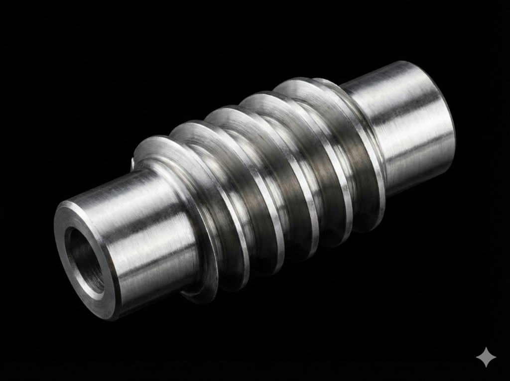
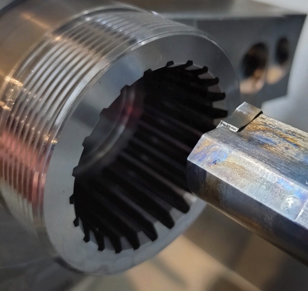
Their primary purpose is to produce a center hole for a lathe or grinding center. They establish a reliable datum and support the workpiece during between-centers machining — which is critical, for example, during precision multi-pass profiling of long worm threads, where any shaft deflection leads to flank profile errors.
There are three main types:
- Type A (Standard, 60° angle): The most common double-ended center drill. It produces a plain 60° cone with a pilot tip. Used for general shafts where the end face is not exposed to impacts or will be faced off in subsequent operations.
- Type B (With 120° protective countersink): Features an additional 120° cone section. It forms a protective chamfer that shields the critical edge of the 60° center seat against mechanical damage during part handling, transport, or storage. Essential when a rough-turned shaft goes to the heat treatment facility and is later ground between centers.
- Type R (Radius / Curved profile): Features an arc profile instead of a straight 60° cone. It ensures optimal, line contact with the center even if there is slight axial misalignment between the spindle and tailstock, or when the shaft flexes slightly under heavy cutting loads.
Type A: 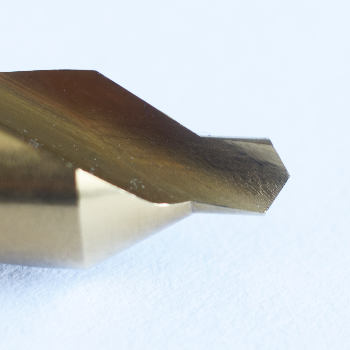 Type B:
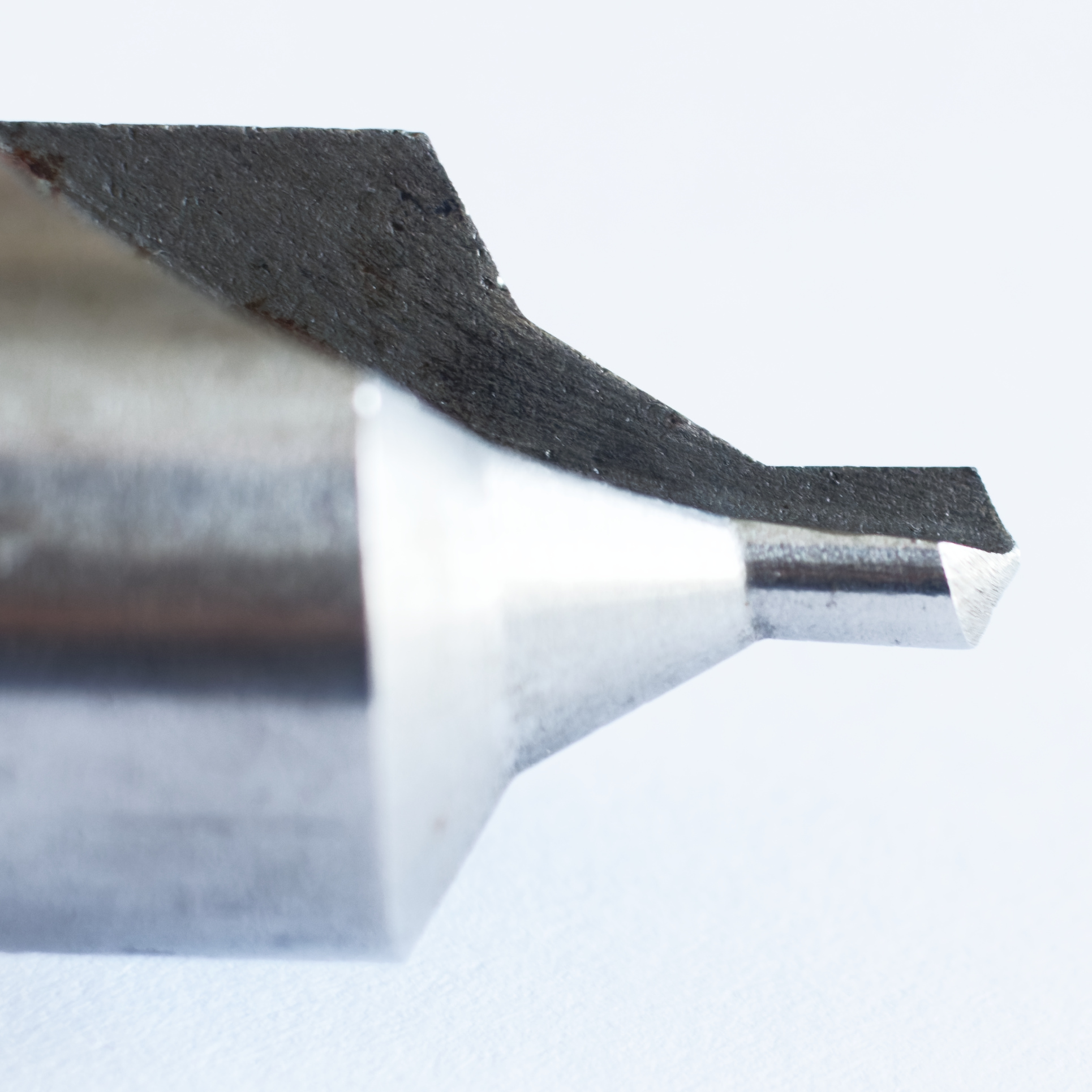 Type R:
2. NC Spotting Drills
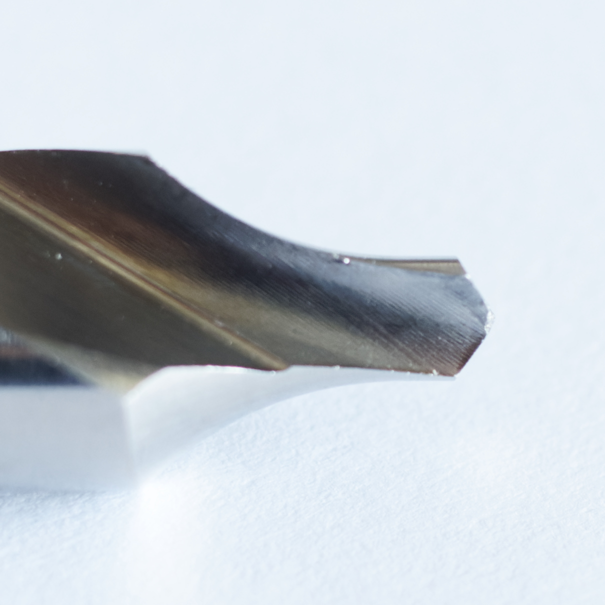
These are rigid, stub-length tools without a thin pilot tip, designed exclusively to establish a rigid center point for a twist drill or to chamfer the hole edge in a single operation.
The golden rule of spotting: the point angle of the NC spotting drill must be equal to or greater than the point angle of the subsequent twist drill.
- For standard HSS drills (118°) – use a 90° or 120° spotting drill.
- For solid carbide (VHM) drills (typically 140°) – use a 142° spotting drill.
Using a 60° or 90° cone for a 140° carbide drill causes the vulnerable outer corners of the drill to strike the sloped walls before the center chisel edge engages. This frequently causes instant chipping of the carbide cutting corners. Keep in mind that modern solid carbide drills with split-point geometry drilling up to 5xD on flat faces generally do not require spotting at all.
3. Workshop Insights and Best Practices
Dwell at the bottom – set it to 3 spindle revolutions
Machining handbooks often discourage using a dwell at the bottom of a hole to prevent work hardening. Workshop reality shows the other side of the coin: retracting the tool the moment it reaches the bottom regularly causes runout due to tool deflection and springback.
Instead of an excessively long dwell that burns the cutting edge, program a pause for exactly 3 spindle revolutions (within the drilling cycle or via G4 calculated from spindle RPM). This is just enough time for the cutting edge to clean up push-off, smooth the cone seat, and eliminate datum runout without work-hardening the steel.
Alignment: Lathe vs. Milling Machine
The impact of tool holder misalignment depends entirely on what rotates:
- Lathe turning (stationary tool in the turret, rotating workpiece): Holder misalignment relative to the spindle centerline is fatal to tool life. The thin pilot immediately suffers bending stress and snaps. However, it has less impact on center hole runout, because the spinning workpiece forces its own axis of rotation, cutting a relatively concentric cone.
- Driven tooling / Milling (rotating tool): Here the opposite is true — any tool holder misalignment or runout transfers directly into runout of the center hole.
Recutting the center hole after roughing
Heavy rough turning releases internal stresses in the material, and high cutting forces can slightly shift the workpiece in the chuck jaws.
On shafts requiring tight tolerances, an excellent shop practice is to drill a rough center hole at the start, rough out the stock, and then re-cut the center cone with a light finishing pass before final operations. If the component is destined for a cylindrical grinder between centers, this quick operation saves massive setup time correcting radial runout.
Check out my software EvoSpline NC Generator: